
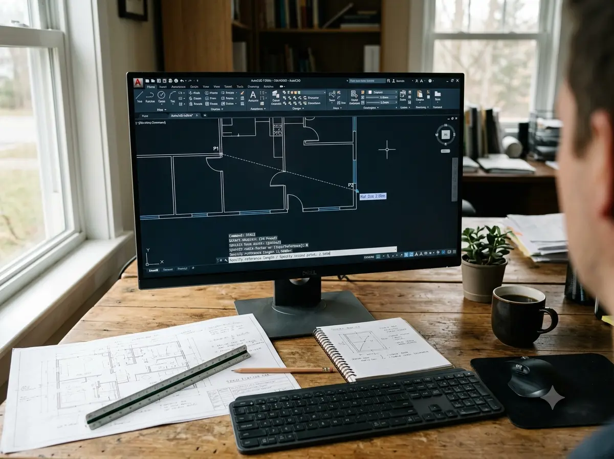
How to Scale with Two Reference Points in AutoCAD
A complete step-by-step guide on scaling by reference and alignment in AutoCAD without calculating scale factors manually.

Ever stood on a site plan, coffee in hand, wondering why earthwork volumes never match up between field estimates and office models?
Calculating site earthwork is far more than just clicking buttons in a software suite, it is about keeping projects profitable, avoiding double costs on dirt hauling, and ensuring you do not overspend on imported fill material.
If you have tried searching online to learn AutoCAD workflows for site grading and surface analysis, you have probably noticed that top guides leave massive gaps. Most articles either toss a quick command at you or spend paragraphs describing basic contour lines without demonstrating how to verify raw output accuracy.
Let us clear up the noise right now like an elder guide who has already walked this ground, stumbled over the pitfalls, and knows exactly where the shortcuts are.
Quick Answer
To execute cut and fill calculations in AutoCAD Civil 3D, create two distinct TIN surfaces: an Existing Ground (EG) surface and a Finished Ground (FG) design surface. Next, open the Analyze tab, navigate to the Volumes Dashboard, and choose Create New Volume Surface. Select EG as your Base Surface and FG as your Comparison Surface. Civil 3D will automatically compute elevation differences across overlapping triangles, generating instant cut, fill, and net earthwork totals.
If you review existing tutorials online, you will notice three major shortcomings:
Let us dive right into the core technical workflow.
When you start setting up your first surface model, you will naturally feel a surge of momentum. You will bring in survey points, build a clean existing ground mesh, and think, “Wow, this earthwork modeling stuff is a breeze!”
Then the middle of the process hits. Your surface boundaries clash, your fill values look totally off because of a missing boundary polyline, or a single rogue point pulls your entire surface down to zero elevation. That is completely normal! Take a breather, double-check your survey input layers, and jump back in with fresh energy.
Before building any surface elements, audit your survey points or imported DWG lines:
0.00) nodes. A single $Z=0$ node pulls your TIN mesh downward like a massive funnel.EG_Surface (Existing Ground).EG_Surface $\rightarrow$ Definition, right-click Point Groups or Contours, and assign your survey data.FG_Surface (Finished Ground / Proposed Site).Here is where your actual cut and fill calculations in AutoCAD take shape:
TIN Volume Surface.EG_Surface.FG_Surface.┌────────────────────────────────────────────────────────┐
│ TIN Volume Surface Setup │
├────────────────────────────────────────────────────────┤
│ Base Surface (Existing) ──► [ EG_Surface ] │
│ Comparison (Proposed) ──► [ FG_Surface ] │
│ │
│ Cut Factor ──► 1.00 (Standard Bank) │
│ Fill Factor ──► 1.15 - 1.20 (Comp.) │
└────────────────────────────────────────────────────────┘
For a complete visual walkthrough covering surface creation, volume analysis, and section generation in civil workflows, check out this comprehensive video tutorial:
Civil 3D Cut and Fill Volume Calculation Tutorial
Numerical output tables work well for civil calculations, but field teams and project stakeholders prefer clear visual heatmaps showing exact cut and fill boundaries across the site.
Elevations.2.If you are operating basic AutoCAD without Civil 3D tools, you can still perform cut and fill calculations using the traditional cross-section method:
\[\text{Volume} = L \times \left( \frac{A_1 + A_2}{2} \right)\]Where:
AREA command or join closed cut/fill boundaries into polylines (PLINE), reading area values from the Properties window (Ctrl + 1).Inside the Volumes Dashboard, select your active volume surface and click Generate Cut/Fill Report. This produces an XML/HTML summary that imports directly into Microsoft Excel spreadsheets.
A zero volume output typically indicates that your Base Surface and Comparison Surface do not geographically overlap, or one of the surfaces lacks valid 3D point elevations. Ensure both surfaces share the exact same spatial coordinate system.
A TIN Volume Surface calculates elevation differences by pairing triangular surface nodes, providing maximum precision on rugged or highly contoured terrain. A Grid Volume Surface samples changes across a uniform grid matrix, making it ideal for large, relatively flat grading sites.
A complete step-by-step guide on scaling by reference and alignment in AutoCAD without calculating scale factors manually.
Confused between engineering software AutoCAD and BIM? Here is a clear, real-world comparison of CAD drafting vs BIM workflows, career impacts, and...
An honest breakdown of how difficult is it to learn AutoCAD, common beginner mistakes, and a practical guide to mastering 2D drafting....
Free, short and practical. No spam, unsubscribe anytime.
Thanks! You are on the list.