
Engineering Software AutoCAD vs BIM: The Honest Truth No One Tells You
Confused between engineering software AutoCAD and BIM? Here is a clear, real-world comparison of CAD drafting vs BIM workflows, career impacts, and...
So, you are sitting in front of your screen with an imported site plan, a PDF blueprint, or an unscaled CAD block, and the dimensions are completely out of whack.
Maybe you tried multiplying numbers on a calculator, typing in random scale factors like 0.0254 or 12, and watching your drawing either shrink into a microscopic dot or explode across Model Space.
Take a deep breath and step away from the calculator!
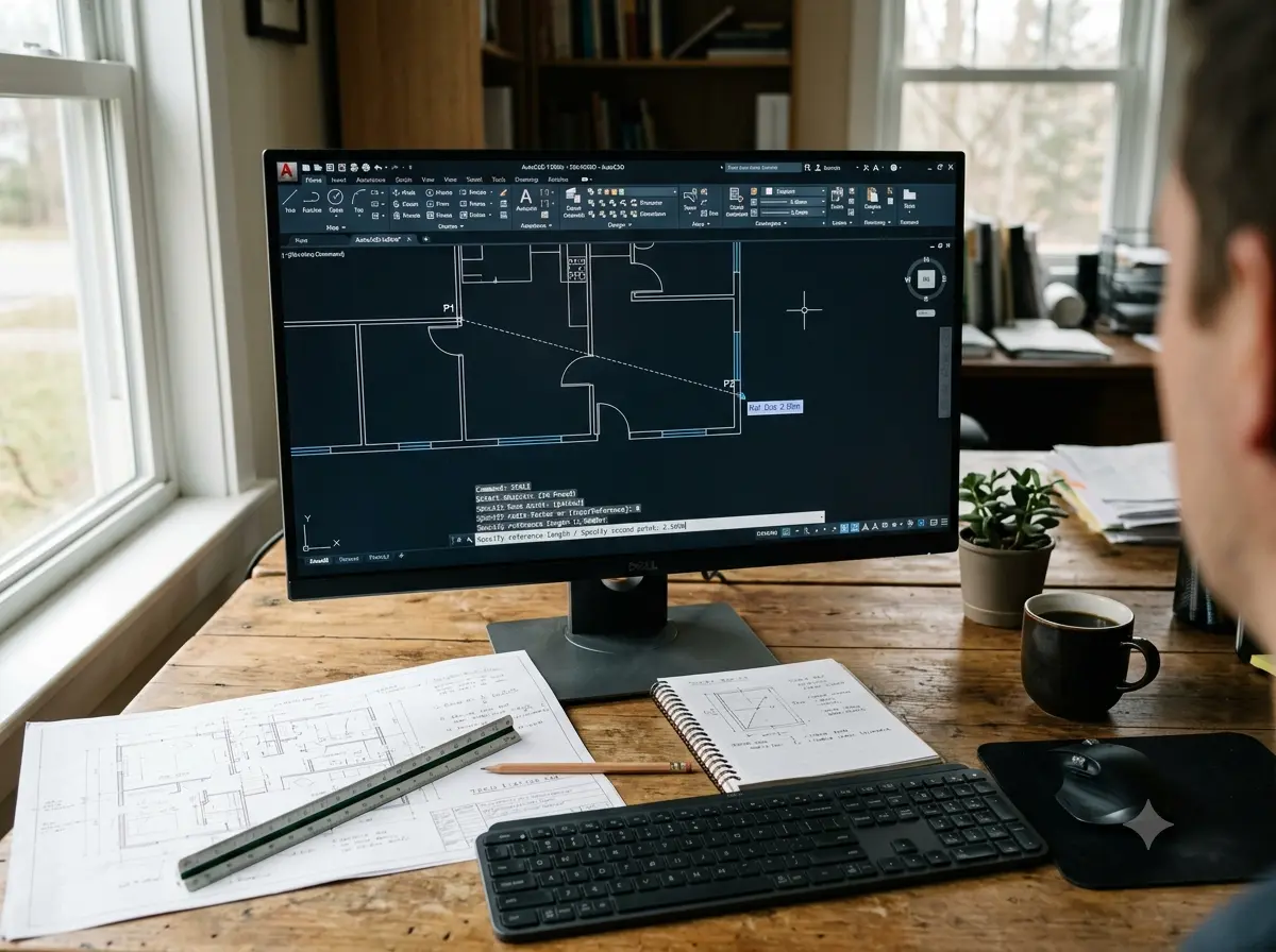
As an elder brother who has spent late nights fixing broken CAD files and making all the beginner mistakes for you, let me tell you a secret: AutoCAD can calculate the exact scale for you. You do not need to do any math. By using two reference points, you simply show AutoCAD what length an object currently is, tell it what length it should be, and let the software handle the rest.
Scaling and aligning objects efficiently comes naturally once you build basic keyboard muscle memory. If you are trying to gauge your overall progress, our guide on how long it takes to learn AutoCAD 2D breaks down the exact 4-week roadmap to reach workplace speed.
Now, let us walk through scaling with reference points step by step so you never have to guess a scale factor again.
To scale an object using two reference points in AutoCAD:
When you import an external image, survey drawing, or architectural plan into AutoCAD, you rarely know its exact scale factor.
Using the standard SCALE command prompts you for a numeric factor. Entering 2 doubles the size, while 0.5 cuts it in half. But what if your imported line measures 3.472 units and needs to be exactly 10.0 feet? Working out 10 divided by 3.472 gives you an infinite decimal number that introduces rounding errors into your construction drawings.
Scaling by two reference points eliminates rounding errors completely. It provides millimeter accurate precision every single time.
This is the classic technique you will use 90% of the time when you know a single real-world distance, such as a doorway width, property boundary, or grid line.
Type SC or SCALE in the command prompt and press Enter.
Click or drag a selection window over all the objects and imported images you want to resize. Once everything is selected, press Enter.
Left-click a point on the object that should stay in place. This base point acts as the anchor around which the rest of the geometry expands or contracts.
Look down at your command bar. Instead of entering a scale factor number, type R and press Enter.
Click the first point at the start of your known line, then click the second point at the end of that same line. You have now told AutoCAD: “This is the current distance I want to fix.”
Type the exact dimension you want that line to be (for example, type 12 for 12 inches or 3500 for 3500 mm) and press Enter.
Your entire drawing will instantly scale to match.
Now, here is something most basic blogs completely fail to teach you.
When you import an unscaled image or block, it is almost never aligned horizontally or vertically. If you use Method 1, you have to scale the object first, and then run the ROTATE command to straighten it out.
Why take two steps when you can do both in five seconds?
The ALIGN command allows you to pick two source points on your unscaled object and map them directly to two destination points on your drawing grid. AutoCAD then moves, rotates, and scales the object all at once!
Boom! Your object snaps directly into position, rotates to the correct angle, and scales to the exact length between your destination points.
Let us walk through a scenario every architectural and civil drafter encounters.
You receive a PDF site plan from a client. You attach it using XATTACH or drag it into Model Space. There is a dimensional callout on a wall reading 20’-0” (20 feet), but when you measure it with the DIST command in AutoCAD, it reads 4.23 units.
Here is how you fix it step by step:
Now your entire PDF is calibrated 1:1 with real-world units, allowing you to trace over it with confidence.
If you are new to the software and wondering if picking up these concepts takes months, check out our honest breakdown on is AutoCAD hard to learn? to understand the realistic learning curve.
If you want a quick visual walkthrough of how this reference workflow handles alignment on real drawings, you can watch this step-by-step breakdown on how to scale with reference points in AutoCAD.
When scaling goes wrong, it usually comes down to a few hidden settings. Keep these tips in mind whenever your drawing behaves strangely:
END) or Intersection (INT) snaps are active.A Scale Factor is a mathematical multiplier. For instance, a scale factor of 2 doubles the object’s size, while 0.5 reduces it by half. Reference Scale allows you to resize objects visually by specifying an existing distance and typing the new target dimension, eliminating the need to calculate scale factors manually.
When you scale an unscaled object (like expanding a small PDF up to a 100-foot site plan), the object expands dramatically outside your current viewport screen. Simply double-click your mouse scroll wheel, or type Z press Enter, then E press Enter (Zoom Extents) to bring your newly scaled drawing back into full view.
The standard SCALE command scales objects uniformly across both X and Y axes. To scale along a single axis, turn your object into a temporary Block (Type B). Select the block, open the Properties Panel (Ctrl + 1), locate the Scale X or Scale Y field, and modify only the axis value you wish to stretch.
Hatch patterns inside enclosed areas do not resize properly with standard geometry scaling if their properties are fixed. To scale a hatch, select it, go to the Hatch Editor tab on the ribbon, and adjust the Hatch Pattern Scale property directly, or re-apply the hatch after scaling your outer boundaries.
Yes! The ALIGN command is significantly faster for imported drawings, survey files, and PDF attachments. While SCALE only resizes objects, ALIGN combines moving, rotating, and scaling across two reference points into a single command.
To verify that your scaling was successful, type DIST (Distance) and press Enter. Click the two endpoints of your scaled reference line. The command line will display the true length, allowing you to confirm that it matches your target real-world dimension.
Confused between engineering software AutoCAD and BIM? Here is a clear, real-world comparison of CAD drafting vs BIM workflows, career impacts, and...
An honest breakdown of how difficult is it to learn AutoCAD, common beginner mistakes, and a practical guide to mastering 2D drafting....
An honest guide on learning AutoCAD 2D speed, a realistic 4-week roadmap, and how to build true drafting speed.
Free, short and practical. No spam, unsubscribe anytime.
Thanks! You are on the list.