
How to Change Units in AutoCAD: The Complete Guide (Zero Scaling Errors)
Learn how to change units in AutoCAD step-by-step. Discover how to use UNITS, -DWGUNITS, and DIMSTYLE to scale drawings and blocks without...
Ever had one of those long drafting sessions where you are working through a massive floor plan or civil schematic, and you suddenly realize you’ve manually drawn the exact same fixture, door, or symbol thirty times in a row?
It gets repetitive pretty fast, doesn’t it?
When learning the ropes especially if you’ve recently pondered how hard AutoCAD is to learn, discovering blocks is usually the exact moment where drafting transforms from tedious line work into a smooth, efficient workflow.
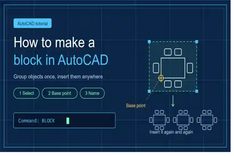
Whether your goal is figuring out how to make a block in AutoCAD for your current drawing layout or understanding how to make a block on AutoCAD to save into an external library for long-term projects, this guide breaks down every step in a clear, practical way.
Quick Answer
How do you make a block in AutoCAD?
- Draw your geometry in the workspace.
- Type
BLOCK(or pressB) and hit Enter.- Assign a name to your block in the Block Definition window.
- Select Pick Point to choose an insertion base point.
- Click Select Objects to highlight all lines and shapes to include.
- Choose Convert to block and click OK.
If you skim through standard CAD documentation, the advice usually boils down to typing BLOCK, selecting a few objects, and hitting enter.
While that gets a block on your screen quickly, it leaves out crucial setup steps. Skipping these details leads to common annoyances: blocks jumping to random (0,0,0) coordinates upon insertion, blocks refusing to match layer colors, or scaling issues across different project files.
Addressing these foundational details right when you build your block ensures clean, reliable behavior every time you place it.
WBLOCK)Before jumping into the command prompt, it helps to distinguish between the two main ways AutoCAD stores block data:
BLOCK command / Shortcut B): Saves the block definition strictly inside your active .dwg file.WBLOCK command / Write Block): Exports selected objects or internal definitions out into an individual .dwg file on your storage drive, making it usable across any drawing file.| Feature | Internal Block (BLOCK) |
External Block (WBLOCK) |
|---|---|---|
| Command Shortcut | B |
W or WB |
| Scope | Current file only | External .dwg file on disk |
| Best Application | Repeating symbols within one drawing | Standardized libraries, details, title blocks |
| Storage Location | File database | System folders or network servers |
Here is the most reliable way to construct an internal block step by step:
Draft your object using standard geometry tools (lines, polylines, arcs).
Crucial Step: Select your finished lines and move them onto Layer 0 before converting them into a block. Geometry created on Layer 0 automatically adopts the color, linetype, and layer properties of whichever active layer you place the block on later.
Type B or BLOCK into the command line and press Enter. The Block Definition menu will open.
In the Name input field, give your block a clear name (for instance, Desk_Office_60x30 rather than a generic tag like block1).
In the Base Point section, click Pick Point. Select a precise object snap on your drawing, such as a corner, midpoint, or center point.
Note: Skipping this step forces AutoCAD to default the base point to coordinate origin (0,0,0), which causes newly inserted blocks to land far off-screen.
In the Objects section, click Select Objects. Highlight all the shapes and lines meant for the block, then press Enter. Set the behavior option to Convert to block.
Click OK. Your selected shapes are now combined into a single, structured block in AutoCAD.
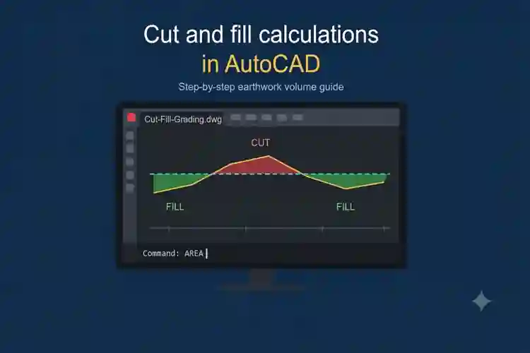
WBLOCK)When you create a symbol you plan to reuse across multiple drawings—like standard structural callouts or site components used during a cut and fill calculation in AutoCAD, saving it externally is the way to go:
WBLOCK (or W) and press Enter.Seeing the workflow in action can make these steps even clearer. This overview covers block creation and editing techniques step-by-step:
Watch: How to Create and Edit Blocks in AutoCAD on YouTube
BE) to assign parameters like stretching, flipping, or rotation states, enabling one block to handle multiple size options.PURGE command periodically to clear out unreferenced block definitions.The keyboard shortcut for creating an internal block is B (for BLOCK). To write a block out to an external drawing file, the shortcut is W (for WBLOCK).
This happens when an explicit base point was not set during block creation. AutoCAD assigns coordinate origin (0, 0, 0) as the default base point when one isn’t picked, placing the point far from where your geometry actually sits. Always use Pick Point during creation.
To rename a block definition inside your active drawing, type RENAME (or REN) into the command prompt and press Enter. Select Blocks under the object type list, click on the existing block name, type your updated name into the Rename To: field, and click OK.
Deleting a block instance from your workspace using the ERASE command removes the visible geometry, but the block definition remains inside your file’s database. To erase the block entirely, run the PURGE command, expand the Blocks tree, select the block definition you wish to eliminate, and click Purge Selected Items.
Yes. Double-click any instance of the block to launch the Block Editor (BE), or right-click the block and choose Edit Block In-Place (REFEDIT) to adjust lines without leaving your main workspace.
If original line geometry was drawn on a specific layer (e.g., Layer 1 with an explicit color assignment) prior to block creation, it retains those fixed properties. For a block to adapt dynamically to whichever layer it lands on, ensure all lines are placed on Layer 0 with color properties set to ByLayer before converting them.
Learn how to change units in AutoCAD step-by-step. Discover how to use UNITS, -DWGUNITS, and DIMSTYLE to scale drawings and blocks without...
A complete step-by-step guide to mastering cut and fill calculations in AutoCAD Civil 3D, earthwork volume dashboard workflows, and site grading precision....
A complete step-by-step guide on scaling by reference and alignment in AutoCAD without calculating scale factors manually.
Free, short and practical. No spam, unsubscribe anytime.
Thanks! You are on the list.