
How to Choose a Jetson Module
Learn how to choose a Jetson module: compare Orin Nano, Orin NX, AGX Orin and Thor by memory, power, JetPack support and...
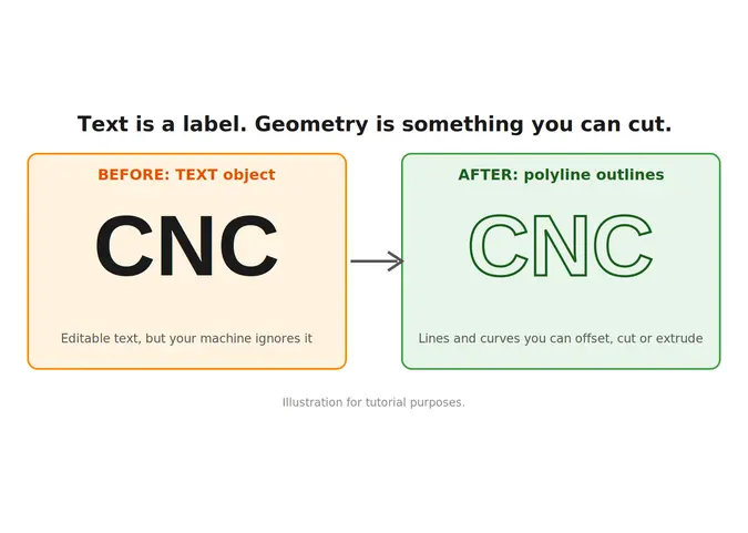
You typed a name, a logo or a part number into your drawing. It looks perfect on screen. Then you send it to the laser cutter, or try to extrude it, and nothing happens. The machine ignores it, or the software complains that there’s no usable geometry.
Welcome to one of the most common “why won’t this work?” moments in AutoCAD. The reason is simple, and so is the fix. AutoCAD text is a label, not a shape, and you have to convert it into lines and polylines before a CNC, a laser or an extrude command can use it. If you’re still getting comfortable with the software, is AutoCAD hard to learn? will tell you this is normal.
Short Answer: How do you convert text to sketch geometry in AutoCAD?
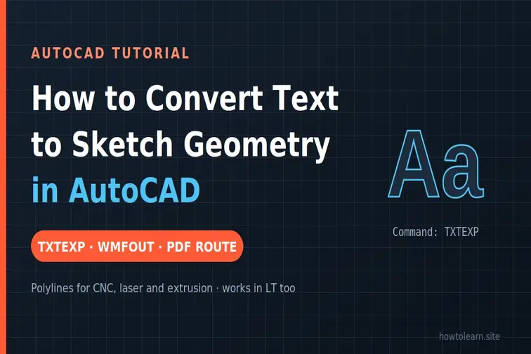
In full AutoCAD, type TXTEXP (Express Tools, Text, Explode Text), select the text and press Enter. It becomes polylines and lines you can edit like any other geometry. In AutoCAD LT, where Express Tools aren’t available, use WMFOUT, then WMFIN, then EXPLODE, or export a PDF with “Convert all text to geometry” and import it back. For smoother curves, use the PDF route.
That’s the whole idea. Now let’s choose the right method for your situation, because the “right” one depends on your AutoCAD version, your font and what you’re making.
Here’s a small confession about the keyword. “Sketch” is the word Fusion and Inventor use. AutoCAD doesn’t have sketches in the same sense. What people usually mean by it is plain geometry: lines, arcs and polylines (and sometimes regions or hatches) that stand in for the shape of each letter.
So when you convert text to sketch geometry in AutoCAD, the real goal is to turn each letter into outlines you can:
If you’re heading into Fusion or Inventor, there’s a section for you near the end.
A thirty-second check saves an hour of frustration.
TXTEXP won’t work there.TXTEXP.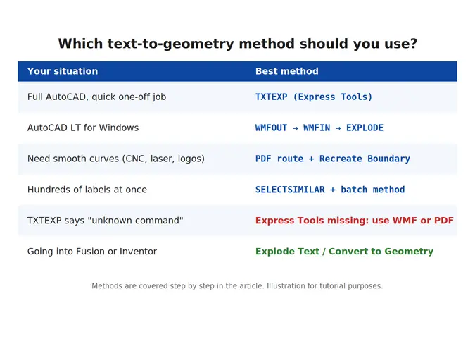
This is the one most people should try first. It’s the Express Tools command called Explode Text.
TXTEXP in the command line and press Enter.Z, Enter, E, Enter), since the converted geometry can land off screen.A few things worth knowing:
EXPLODE), then run TXTEXP.No Express Tools? This old trick still works in AutoCAD LT for Windows, and in full AutoCAD too. TXTEXP itself relies on the same WMF idea, so the results are similar.
WMFOUT, select the text, and save a file.WMFIN, pick the file you just saved and place it. Several guides insert it at scale 2, so check the size against the original.EXPLODE and select the imported block. The text should now be lines and polylines.Two warnings: AutoCAD LT for Mac doesn’t have WMFOUT, and WMF generally works best with SHX text (TrueType needs the width trick above).
This is the method I’d reach for when curves matter. Several users on the Autodesk forums prefer it because the outlines come out smoother, and the continuous polylines have more vertices than TXTEXP produces.
EXPORTPDF or Plot to PDF). In the PDF Options, tick Convert all text to geometry.PDFIMPORT and bring the PDF back in. Make sure solid fills are included in the import, so the letters arrive as filled shapes.HATCHEDIT, pick the hatch and choose Recreate Boundary, then choose Polyline as the object type.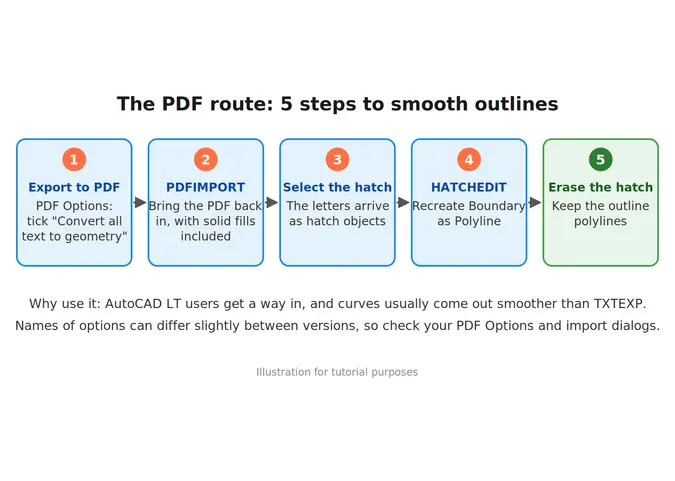
It takes a few more clicks, but the result is the closest thing to a true outline. Dialog names can differ a little between AutoCAD versions, so look for the equivalent options in your PDF Options and import windows.
Got 1,200 tags to engrave? Don’t click each one.
SELECTSIMILAR or a window to select all of it. Isolate the layer so you only grab text.TXTEXP, select everything in one go).REGION and merge them with UNION. That gives you solid shapes rather than open outlines.Exploding the text is only half the job. Here’s what to check afterward.
PEDIT, then Join (or the JOIN command) so each outline is one continuous polyline.And if you’re building your skills from scratch, the step-by-step AutoCAD 2D learning guide shows where tools like this fit into everyday drafting.
If you want true sketch geometry inside Autodesk’s 3D tools, the commands live in those programs.
A neat workflow: convert in AutoCAD, then bring the polylines into Fusion or Inventor as part of a DWG.
Let’s go through the usual suspects.
TXTEXP turned a TrueType curve into short segments. Switch to a TrueType font, or use the PDF route for smoother curves.EXPLODE the imported block.WMFOUT, so try the PDF route, or open the DWG in a vector program and export outlines (check what your version supports).For more guidance, you can watch this video: How to convert text to geometry in AutoCAD video.
Q1: What is the command to convert text to geometry in AutoCAD?
TXTEXP, the Explode Text tool in Express Tools. It converts text into polylines and lines.
Q2: How do I convert text to geometry in AutoCAD LT?
LT doesn’t include Express Tools. Use WMFOUT, WMFIN and EXPLODE (Windows), or export a PDF with “Convert all text to geometry”, import it back, and recreate the hatch boundary as polylines.
Q3: Why does TXTEXP turn my text into straight lines? SHX fonts are stick fonts made of straight strokes, and TrueType curves can become short segments. For smoother outlines, use the PDF route.
Q4: Can I turn text into a polyline in AutoCAD?
Yes. TXTEXP produces polylines, and the PDF route gives you polyline outlines through HATCHEDIT and Recreate Boundary.
Q5: Can I convert text to geometry for a laser cutter or CNC? Yes. Convert it, join the segments, make sure inner and outer outlines are closed, check your units, and test on one word first.
Q6: How do I convert AutoCAD text to sketch geometry in Fusion? In Fusion, right-click the text in an active sketch and choose Explode Text. In Inventor, right-click the sketch text and choose Convert to Geometry.
Q7: Can I convert the geometry back into editable text?
Not simply. Keep a copy of your original text before converting. If you only have lines, there’s a PDF-based command (PDFSHXTEXT) that can attempt a reverse conversion for some cases, but it’s far from a one-click undo.
Learn how to choose a Jetson module: compare Orin Nano, Orin NX, AGX Orin and Thor by memory, power, JetPack support and...
Learn how to change units in AutoCAD with UNITS, -DWGUNITS and DIMSTYLE, plus scale factors and fixes for drawings that didn't resize....
Learn how to rename a block in AutoCAD with the RENAME command, wildcards, and -RENAME, plus quick fixes when a block won't...
Free, short and practical. No spam, unsubscribe anytime.
Thanks! You are on the list.